Drop-down spherical radiation reflector. Types of reflectors: what controls the light
The simplest and most common accessory in studio photography is a reflector. The beautiful word “reflector” is translated as reflector. Accordingly, the essence of his work is the reflection of light.
A reflector is used to turn non-directional light into directional light. You can understand the operating methodology of reflectors from these diagrams, which have not yet been found on Russian-language photographic resources. Well... It's time to close this gap too.
I will briefly describe all the main options for reflectors so that you can further understand not only photographic reflectors, but also any others. For example, in reflectors for car headlights, lanterns, etc.
The article turned out to be relatively long because... reflectors “this is our everything.” I would recommend taking a closer look at the light output diagrams from the reflector and the comments for each reflector. For the reason that the cut-off pattern depends on the distance and size of the reflector, and the diagrams show the principle itself, with the help of which you can understand what to generally expect from the reflector by moving it.
There are no analogues of this article on photographic resources. There are only light spots, but the principle of operation of reflectors is not described anywhere. All information was gleaned from specialized sources, such as the “Carl Zeiss campus”, websites of manufacturers: car headlights; lanterns and spotlights; telescopes, websites of various universities, etc.
I would be glad if experts in the field of designing reflectors and lighting devices constructively comment on the article and maybe add or correct something. I would also be grateful for 3D modeling of light sources if anyone wants to help design the article beautifully (3Dmax, Maya, Pro/ENGINEER aka PTC Creo Elements/Pro, etc.). You can even pay a little and cooperate in the future if you are satisfied with the result.
All reflectors are kindly provided by the company Falcon Eyes.
What you need to know about reflectors
The nature of the luminous flux when using a reflector depends on:
— its geometric shape and size;
— properties of its surface;
— lamp location;
— distance to the lighting object.
Reflector operation schemes

Super-brief educational program on geometry
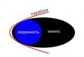
A ball is a volumetric circle. A sphere is the surface of a ball. If we rotate the parabola, we get an elliptical paraboloid. A circle is a special case of an ellipse. All these figures are conic sections.
Spherical reflector
The lamp is in the center of the reflector.

spherical reflector, lamp in the center

hemisphere
If you place the flash lamp in the center, the light will be reflected back into the lamp. This increases the luminous flux output by approximately 40%. But since the rays diverge quite widely, such a reflector is not very convenient to work in studio photography.
The lamp is in the focus of the reflector.

spherical reflector, lamp in focus
The sphere on which the reflector's focal point is located is defined as half the radius of the reflector. In this case, the output will be parallel rays, which is good for uniform illumination. This reflector is often used in flashlights in conjunction with a Fresnel lens.
The most famous and widely used spherical reflector is (beauty dish).
There is no guarantee that the lamp in your particular beauty dish is in focus. There are as many shapes, sizes and positions of beauty dish lamps as there are manufacturers. You yourself will be able to evaluate what you have knowing the principle.


Another example of a spherical reflector is a photo umbrella. It is attached to the flash with its rod and produces soft but poorly controlled light.

photographic umbrella
A photo umbrella is used due to its compactness and low cost. The photo umbrella also has the ability to move relative to the flash. The inner surface of the umbrella can be silver, gold or matte white. Silver surfaces produce a harsher light, while matte white surfaces produce a softer light.
There are also umbrellas “for light”, but this is no longer a reflector, which is discussed in this article, but a diffuser, so I will not present it here.
I’ll add more about photo umbrellas later, once I’ve taken test pictures.
Parabolic reflector
This type of reflector can also collect rays and direct them in parallel if the light source is in the focus of the reflector.

parabolic reflector with a lamp at focus
If the lamp is brought closer from the focus to the reflector, the rays will diverge, and if they are moved away from the focal point, they will converge.

paraboloid
Examples of using a parabolic reflector in studio instruments.

Let's move on to the most stunning reflector. Not by its characteristics (each tool has its own task), but by its size! Here I will call parabolic reflectors “PARA”, after the name of the most popular parabolic reflector - Broncolor PARA. Some photographers use PARA mainly to shock the client and convince them that this is a serious studio.
Areas of use: PARA is widely used in the West in location shooting, i.e. in outdoor shooting. Since it is foldable, despite its large size it can be folded quite compactly for transport by car. Its advantage is the soft light and the fact that the photographer can stand directly between the PARA and the model without practically changing the cut-off pattern (i.e. it actually blocks part of the light, but due to the size of the PARA this is not significant). PARAs come in a variety of brands from cheap (within reason) to very expensive and desirable ones.
Elliptical reflector

Special types of reflectors
In addition, there are special types of reflectors that are used for specific tasks.

Conical nozzle Falcon Eyes DPSA-CST BW
Application area The background nozzle follows from its name; it serves to illuminate the background. Thanks to its shape, it illuminates the background more softly than, for example, a standard elliptical reflector.

It didn’t turn out to be a perfectly beautiful shot (the background is a little uneven), but the essence is clear. The background nozzle distributes the light flux more evenly.
Results:
In this article I touched on only a few types of reflectors. It is clear that if we take such a comprehensive concept as “reflector”, then we can write about different types of reflectors for a long time. And in the following articles we will continue to get acquainted with different types of reflectors.
You have become acquainted with basic studio reflectors, the principles of their operation and their classic applications. The scope of application is actually limited only by your imagination and the capabilities of a particular reflector.
update
When coming to a photo studio, I recommend using slang names for reflectors. For example, if you need a large parabolic reflector, it is called PARA (“Pair”, large umbrella).
If you want a small elliptical, it's called a "standard reflector" or "pot."
A beauty dish is a beauty dish. In English, Beauty Dish (“plate for beauties” :)).
There is also a softbox, stripbox, octobox, etc. which will be discussed in the following articles because These are no longer just reflectors, but separate devices.
I will be glad to hear your comments and see examples of your work with various reflectors.
There will be a new article on studio accessories coming soon! Stay in touch:)
Let's let the girl go... let her float...

shot using a beauty dish in cloudy weather
The patented utility model relates to space technology, namely, to spherical reflectors with a mesh surface deployed in orbit, which are a calibration artificial earth satellite (AES). According to the patented utility model, the power frame of the reflector is made in the shape of a sphere formed by meridian ribs, which are made of rod elements connected to each other by meridian hinges. To impart the necessary rigidity, the power frame of the spherical reflector contains an equatorial belt connecting the middles of the meridian ribs. The equatorial belt is made of rod elements connected to each other by equatorial hinges, and the radio-reflective surface mounted on the surface of the load-bearing frame is made of metal mesh fabric. The power frame contains from 8 to 36 meridian ribs, each meridian rib contains from 8 to 36 rod elements connected to each other by meridian hinges, the equatorial belt contains from 8 to 36 rod elements connected to each other by equatorial hinges of two types. The technical result is that the developed utility model makes it possible to significantly simplify the final structural implementation of a spherical reflector, eliminate sufficiently large structural elements, radically reduce the overall dimensions of the reflector when folded, which increases the convenience of its transportation to low-Earth orbit, and reduce the requirements for the dimensions of the transport compartment for its delivery into orbit. 7 p.f., 10 ill.
The patented utility model relates to space technology, namely, to spherical reflectors with a mesh surface deployed in orbit, which are a calibration artificial earth satellite (AES).
The developed spherical reflector can be effectively used to solve a variety of applied and scientific problems, in particular, as a reference target with a precisely known value of the effective scattering area (RCS) when testing and monitoring the functioning of radar stations (radars) with the requirements for accuracy characteristics specified for it and by energy potential, to determine with high accuracy the coordinates of space satellites in orbit, to assess the reflection characteristics of multi-band radar equipment.
It is known that the best objects for full-scale radar calibration are reflective spherical surfaces of various diameters. To effectively solve the constructive problem of creating a drop-down space reflector, the applicant analyzed numerous technical solutions in this area, varied in their final implementation.
For example, various designs of “umbrella-type” reflectors are known (US patents 2945234; 3286259; 4482900; 5446474;
5864324; 5680125;6028570).
A common characteristic disadvantage of patented solutions is their structural complexity and large overall dimensions when folded, which significantly limits the scope of their effective application.
A deployable large-sized space reflector is known (RF patent 2266592; H01Q 15/16). The invention relates to deployable large-sized reflectors of space antennas. The technical result consists in minimizing the height of the reflector in the transport position, which is achieved by making the power ring of the reflector in the form of a pantograph with telescopic stands. The disadvantage of the known design is the complexity of the design and the increased overall dimensions of the device when folded.
A deployable large-sized spacecraft reflector is also known (RF patent 2350519; H01Q 15/16).
The invention relates to space mirror antennas with a deployable umbrella-type reflector having a diameter of about 12 m or more. The reflector contains a central unit in the form of a coaxially located base and flange, as well as a load-bearing frame mechanically connected through a form-building structure to the mesh fabric. The load-bearing frame is formed from straight spokes hinged to the base, made in the form of mesh rod structures with consoles attached to their ends.
The technical result of the invention is to provide a high-precision profile of the working surface of the reflector (standard deviation from the theoretical profile is not more than 1.3 mm) after all types of tests simulating its operating conditions, as well as to simplify the design and reduce the weight of the reflector.
The characteristic disadvantage of the patented solution is the traditionally complex design and significant overall dimensions when folded.
Designs of umbrella antennas for spacecraft are also known (RF patent 2370864; H01Q 15/16; RF patent 2370865; H01Q 15/16).
The inventions relate to space technology, in particular to mirror antennas with a deployable large-sized umbrella-type reflector.
The technical result of the invention according to RF patent 2370864 is to expand the operational capabilities of the reflector. The umbrella antenna consists of a feed and a reflector, which includes a central unit, a power frame pivotally connected to it, made in the form of spokes, mechanically connected to the mesh fabric, a hub attached to the central unit on the opposite side of the reflector opening, which is in the area of the free end with using guy ropes, it is connected to the knitting needles by a single center. The technical result is achieved due to the fact that at the free end of the hub there is installed a device for adjusting the shape of the radio-reflective surface of the reflector, the output elements of which are made in the form of screws and are located between a single center and each guy wire, with the ends of which they are mechanically connected with the possibility of rotational movement and independent of each other. other changes in the effective distance from the point of connection of each guy with the spoke to a single center. The longitudinal axes of these output elements mutually coincide with the corresponding axes drawn through a single center and the point of connection of the corresponding guy with the spoke.
The technical result of the invention according to RF patent 2370865 is to increase the reliability of the reflector opening. The umbrella antenna consists of a feeder and a deployable reflector, including a central unit, a power frame connected to it, made in the form of spokes, mechanically connected to the mesh through a form-building structure made in the form of cords and tie-down threads, and a mesh located on the opposite side of the mesh. opening of the reflector on the form-building structure. The technical result is achieved due to the fact that covers are put on the knitting needles, and the mesh is made in the form of screens located between two adjacent knitting needles and made of elastic thin material with low electrical conductivity. The through free cells of the screens are smaller in size compared to the minimum possible cross-sectional sizes of tie threads and cords. Each screen is glued with one radial boundary zone to the surface of the cover of a specific spoke, and with the other radial boundary zone it is connected via Velcro to the outer surface of the boundary zone of the adjacent screen.
The analysis shows that the significant design disadvantages of these devices are their bulkiness when folded and the complexity of the circuit design, which causes low operational reliability of the design when deployed in orbit.
A spherical radiation reflector is known (RF patent 2185695;
H01Q 15/14), which is closest in technical essence and design implementation to the patented utility model, and which is accepted as a prototype.
The radiation reflector described in RF patent 2185695 contains internal and external pneumatic chambers, radial struts made in the form of a flexible tube with holes, on which spherical pneumatic cells made of elastic material are built up, interacting with each other.
To form a rectangular reflector, the pneumatic system is made in the form of a matrix of mutually perpendicular flexible tubes communicating with each other with holes, around which cubic pneumatic cells are built up, interacting with each other and the mirror surface.
The reflector with a spherical surface contains radial and concentric sectional pneumatic tubes mechanically and pneumatically connected to each other. To create them, flexible tubes have holes around which pneumatic cells are built in the shape of a sector of a spherical shell. When the pneumatic cells are inflated, they form a hemispherical reflector shell with a spherical concave surface.
Strips of an electrically conductive metal coating are applied to the base of the pneumatic cells on the convex side, forming electrically conductive rings. These rings are connected to a source of adjustable voltage relative to the metal coating of the mirror surface. Under the influence of electrostatic forces, the mirror surface takes on a spherical shape.
In addition, to reveal a flat-shaped film reflector, the outer ring and radial struts can be made in the form of garlands of hollow balls (or rings) strung on cables, the ends of which are passed through the holes of the rigid inner ring and connected to a mechanism for tensioning and fixing the position of the cables.
A reflector with a spherical surface contains concentric rings in the form of a garland of radiation-reflecting cells in the shape of a sector of a spherical shell, strung on two cables passed through the middles of the opposite side faces of the cells. In this case, the concentric rings are connected to each other by radial cables, and the ends of the concentric and radial cables are connected to a mechanism for tensioning and fixing the position of the cables.
A significant disadvantage of the known spherical reflector according to RF patent 2185695 is its structural complexity and reduced reliability of the deployment process in orbit, which is due to the presence of a large number of its constituent structural elements, the presence of various types of cables and mechanisms for tensioning and fixing the position of these cables, the presence of several pneumatic chambers and their systems inflation, a significant number of dynamically used structural elements.
This utility model solves a technical problem:
Simplifying the design of a spherical reflector,
Increasing the reliability of its deployment in orbit,
Increasing the lifespan in orbit.
The solution to the stated technical problem is achieved as follows.
An drop-down spherical reflector, similar to the reflector described in RF patent 2185695, containing a power frame of hinged rod elements on which the reflective surface is fixed, according to the patented utility model, the power frame of the reflector is made in the shape of a sphere formed by ribs-meridians, which are made of rod elements connected to each other by meridian hinges. It is provided that the meridian ribs are fixed at their ends in oppositely located pole hinges.
In accordance with the patented solution, to impart the necessary rigidity, the power frame of the spherical reflector contains an equatorial belt connecting the middles of the ribs - meridians. The equatorial belt is made of rod elements connected to each other by equatorial hinges.
The patented solution provides that the radio-reflective surface fixed on the surface of the load-bearing frame is made of metal mesh.
According to the patented utility model:
The power frame contains from 8 to 36 meridian ribs, each meridian rib contains from 8 to 36 rod elements connected to each other by meridian hinges;
The equatorial belt contains from 8 to 36 rod elements connected to each other by equatorial hinges of two types.
The power frame is made with a diameter from 1 to 12 meters.
Laser corner reflectors are fixed on the surface of the load-bearing frame.
The patented utility model provides the ability to control the results of autonomous deployment of a spherical reflector in orbit. In this case, the spherical reflector is equipped with sensors in the form of a limit switch, which are mounted on equatorial and meridional hinges, and also contains information channel equipment with its own power source for communication with the spacecraft and ensuring the transmission of command and telemetric information.
The technical result of a patented utility model is that the developed utility model allows:
Significantly simplify the final structural implementation of the spherical reflector, eliminate (inherent to the prototype) sufficiently large structural elements, and accordingly radically reduce the overall dimensions of the reflector when folded, which increases the convenience of its transportation to low-Earth orbit, reduce the requirements for the size of the transport compartment for its delivery to orbit;
Reducing (minimizing) the number of functional elements included in the final design of a spherical reflector significantly increases the reliability of deployment of the reflector in orbit and increases its operational life;
At the same time, the patented design is characterized by increased accuracy and stability of the geometric shape of a spherical reflector deployed in orbit, the radio-reflective surface of which provides high reflection characteristics, which qualitatively improves all the main operational characteristics of the spherical reflector.
The optimal overall dimensions and reduced weight of the developed reflector when folded allow it to be transported to near-Earth orbits by associated launches, which radically increases the economic efficiency of operating the patented design.
The essence of the patented utility model is explained by a description of the developed spherical reflector and graphic materials showing:
Fig.1. - Diagram of a spherical reflector in an expanded state.
Fig.2. - Meridian hinge ((a - side view, b - bottom view);
Fig.3. - Connection of the rod and the meridian hinge ((a - side view, b - bottom view);
Fig.4. - Pole joint.
Fig.5. - Equatorial hinge.
Fig.6. - Connection of rods in the rib-meridian (fragment in the open state).
Fig.7. - Folded state of the rib-meridian.
Fig.8. - Spherical reflector in folded state (view from the pole joint).
Fig.9. - Spherical reflector in folded state (section in the equatorial plane).
Fig. 10 is a block diagram of the information channel equipment with its own power supply for monitoring the results of autonomous deployment of the reflector in orbit.
When deployed, the patented reflector (Fig. 1) is a spherical shell formed by a knitted metal mesh fabric stretched over a self-expanding power frame.
The power frame of the reflector is made in the shape of a sphere and contains (Fig. 1) an oppositely located pair of pole hinges 1, meridian ribs 2, which are made of rod elements 3 connected by meridional hinges 4 (Fig. 2). To ensure folding, adjacent hinges 4 in the meridian ribs are located towards each other (Fig. 6).
All meridian ribs 2 are fixed at their ends in the corresponding pole hinges 1, located oppositely (one opposite the other).
To provide additional rigidity, the reflector's power frame contains an equatorial belt 5 connecting the middles of the meridian ribs 2.
The equatorial belt 5 is made of rod elements 6 connected to each other by equatorial hinges of two types. At the intersection of the meridians and the equator, four-finger equatorial hinges 7 are used (Fig. 5). Between the hinges 7, the rods 6 are connected by two-finger hinges 8, which are similar in design to the meridional hinges 4 (Fig. 2). To ensure folding, the hinges 8 are also installed towards the equatorial pair of hinge pins 7 (Fig.9).
The reflective surface 9, fixed on the surface of the load-bearing frame, is functionally a radio-reflective surface, formed by a knitted metal mesh, made, for example, of tungsten or steel microwire coated with gold or nickel.
When developing this reflector, it was taken into account that the number of partitions along the equator depends on the required accuracy of approximation of the surface of the sphere; the number of partitions along the meridian is equal to the number of partitions along the equator.
Research conducted by the applicant indicates that to ensure the spherical shape of the reflector and the required rigidity, the load-bearing frame:
And the equatorial belt 5 can contain from 8 to 36 rod elements 6, interconnected by equatorial hinges 7 and 8.
The patented utility model provides that the power frame can be made with a diameter of 1 to 12 meters. At the same time, in order to achieve increased accuracy of alignment of the location means, it is possible to place laser corner reflectors on the surface of the power frame (not shown in the figure).
Individual technical elements of a spherical reflector may have the following possible design implementation.
The meridian hinge 4 (Fig. 2) can be made in the form of hinges 10, a body 11, two axes 12 and two springs 13. The hinges 10 are put on the axis 12. The springs 13 are also put on the axis 12 and are located inside the loops 10. One end of the spring 13 are embedded in the body 11, the other in the hinges 10. When folded, the spring 13 is twisted and stores energy for deployment. Rod elements 3 are attached to hinges 10 (Fig. 3).
The pole joint 1 (Fig. 4) consists of a housing 14 and hinges 15 mounted on a ring axis (inside the housing, not shown). The hinges 15 attach the rod elements of 3 ribs-meridians 2.
The equatorial hinge 7 (Fig. 5) serves to connect the rod elements 3 of the meridian ribs 2 and the rod elements 6 of the equatorial belt 5. The equatorial hinge 7 consists of hinges 16, a body 17, axes 18 and springs 19. The axes 18 are fixed in the body 17, loops 16 and springs 19 on axes 18. The rod elements 3 of the ribs-meridians 2 and the rod elements 6 of the equatorial belt 5 are attached to the loops 16. When folding the reflector elements, the springs 19 also store energy for the subsequent deployment of the reflector in orbit.
A fragment of a folded edge-meridian is shown in Fig.7.
To monitor the result of autonomous deployment in orbit, the patented reflector is equipped with sensors in the form of a limit switch, which are mounted on meridional and equatorial hinges, and also contains information channel equipment with its own power source for communication with the spacecraft and ensuring the transmission of command and telemetric information.
The information channel equipment contains (Fig. 10) its own power supply 20, controller 21, cable amplifier 22, cable 23 (length up to 100 meters) connected in series.
To control autonomous deployment in orbit, the spherical reflector (Fig. 10) contains N sensors 24 of the “open contact” type and a multi-core cable 25, through which information about the state of the set of sensors 24 (closed or open) is transmitted to the controller 21.
Sensors 24 in the form of a limit switch (not shown in Figs. 1-9) are mounted on the meridional and equatorial hinges of the spherical reflector (on hinges 4 and 7 and/or 8).
To explain the principle of operation of the plurality of sensors 24, it should be explained that when the spherical reflector is in the folded state, all sensors 24 are in an open state (logical state "0"). When the spherical reflector is opened, all sensors 24 must go into a closed state and current begins to flow through the corresponding wires of the multi-core cable 25 (logical state “1”). Each sensor 24 has its own pair of wires in the multicore cable 25. If, after opening the spherical reflector, at least one of the sensors 24 does not go to the logical state “1”, this means that the corresponding pair of hinges has not fully opened, which is a signal of incomplete (incorrect) opening of the spherical reflector. The signal about this is transmitted through the controller 21, which provides sequential polling of the state of each sensor 24. Then the signal is transmitted through the cable amplifier 22 and the two-wire cable 23 to the information equipment 26 of the launch vehicle stage.
For example, a standard battery or rechargeable battery can be used as its own power source. To implement controller 21, standard circuit designs and corresponding microcircuits are known: current switches (K176KT1, K561KTZ), multiplexers (K561KP2 and KR1561KP2) and decoders (KR1561ID6, K561ID1). Cable amplifier 22 can be implemented on standard microcircuits of the type (K176KT1, K561KTZ, KR1561KTZ).
The information channel equipment with its own power source can be placed, for example, on the inside of one of the pole joints 1. The number of sensors 24 depends on the size of the spherical reflector, on the number of meridian ribs 2 and the number of hinges in the design of the spherical reflector. For example, to achieve the results of autonomous deployment of a reflector in orbit, the number of sensors 24 may be equal to half the number of hinges in the reflector structure.
The applicant considers it necessary to note that specialists working in the field of electronic equipment for spacecraft have appropriate knowledge about the availability of various components for the final implementation of information channel equipment, in addition to those components that are given as possible implementation options.
The specific circuit implementation of the information channel equipment of the patented utility model and the identification of all possible initial components and components for the production of such equipment is not difficult for specialists, since it follows from the state of the art on the basis of practical data and includes well-known standard components and components fixed in various scientific and technical publications and reference books, it should also be noted that the entire element base is mass-produced and available for free purchase, due to which a more detailed disclosure of the initial components and components of the information channel equipment is impractical.
Folding of the patented spherical reflector for its transportation and placement in the transport compartment is carried out in the following sequence.
When folded, the spherical shell of the reflector is transformed into a sphere of smaller diameter. A view of the folded reflector from the side of the pole joint is shown in Fig. 8, along the equatorial section in Fig. 9.
The reflector is fixed to a special device using the pole joints. A technological compressive adjustable harness is applied to the equatorial belt (Fig. 1). All hinge elements 4 of the meridian ribs and hinges 8 of the equatorial belt are folded (Fig. 7) using a technological device, which is a meridian-ring belt structure with an adjustable length of belt rods. In this case, the reflector frame loses stability and is ready to fold. Then, sequentially, according to a certain algorithm, the lengths of the rods of the tape structure and the compression strapping are shortened until the reflector is folded to the state shown in Fig.8 and Fig.9.
The developed spherical reflector is used as follows.
The folded reflector (Fig. 8, Fig. 9) is located under the fairing of the spacecraft (SV). After insertion into orbit and release of the fairing, the reflector is separated from the spacecraft in folded form at a distance that ensures safe deployment, and is opened by the energy of the hinge springs upon command from the control point or on-board unit. The deployment control system transmits information to the control center via a telemetry channel. The opening of the spherical reflector in orbit occurs automatically due to the energy stored in the springs of the hinged elements of the frame when folded. After deployment, the reflector takes the shape of a sphere with a calibrated EPR value (Fig. 1).
The reflector can be used, for example, to calibrate the energy potential of a radar station (radar) and thereby estimate the maximum range of the radar for objects with other ESR values. To do this, after determining the spatial coordinates of the reflector, the radar emits a radio signal of a certain power in its direction and, based on the level of the received reflected signal, receives a calibration value of the radar's energy potential, taking into account the known EPR value of the reflector. Based on the energy potential of the radar obtained as a result of calibration, using the well-known radar range formula, the maximum range of the radar over objects with other ESR values is estimated, which is one of the tasks of radar calibration. Further, by comparing the levels of reflected signals from other objects with the level of the signal from the reflector, it is possible to obtain the values of their ESR, which in some cases is of independent interest.
When accurately measuring the spatial coordinates of the reflector, for example, using laser ranging stations operating on the reflected signals of corner reflectors mounted on a spherical reflector, it can also be used for radar alignment.
Test tests of the patented utility model carried out by the Applicant confirmed:
High performance characteristics of the spherical reflector obtained in real time;
Compactness and optimal weight of the structure when folded for transportation, high reliability of deployment of the device in orbit.
1. An drop-down spherical reflector containing a power frame made of rod elements on which the reflective surface is fixed, characterized in that the power frame of the reflector is made in the shape of a sphere formed by meridian ribs, which are made of rod elements interconnected by meridional hinges, all ribs -meridians with their ends are fixed in oppositely located pole hinges, while to give additional rigidity, the load-bearing frame contains an equatorial belt connecting the middles of the meridian ribs, which is made of rod elements connected to each other by equatorial hinges, and a reflective surface fixed on the surface of the load-bearing frame , made of metal mesh fabric.
2. Drop-down spherical reflector according to claim 1, characterized in that the power frame contains from 8 to 36 meridian ribs.
3. The drop-down spherical reflector according to claim 1, characterized in that each meridian rib contains from 8 to 36 rod elements connected to each other by meridional hinges.
4. Drop-down spherical reflector according to claim 1, characterized in that the equatorial belt contains from 8 to 36 rod elements connected to each other by equatorial hinges.
5. Drop-down spherical reflector according to claim 1, characterized in that the load-bearing frame is made with a diameter of 1 to 12 m.
6. Drop-down spherical reflector according to claim 1, characterized in that laser corner reflectors are fixed to the surface of the load-bearing frame.
7. The drop-down spherical reflector according to claim 1, characterized in that to control autonomous deployment in orbit, the spherical reflector is equipped with sensors in the form of a limit switch, which are mounted on meridian and equatorial hinges, and contains information channel equipment with its own power source for communication with the space device and ensuring the transmission of command and telemetric information.
Using a reflector is a very effective way to control light. Remember how Archimedes, using the copper shields of the defenders of Syracuse, burned the Roman squadron to the ground?
Reflectors collect and redirect rays coming from a light source. A modern reflector is a curved metal or glass surface, processed in accordance with its purpose. For example, smooth mirror reflectors allow efficient collection of light rays and are used in lens spotlights. For lensless devices, diffusion reflectors with a rough surface are more suitable; they provide uniform diffuse coverage.

The shape of the reflector can also be different. Thus, in lens instruments they usually use spherical reflectors, rigidly fixed at a certain distance from the light source. When focusing, the entire block moves relative to the lens, and the light intensity remains constant.
Parabolic a reflector is an indispensable attribute of PAR lamps. Such lamps can generate beams of light of different widths, it all depends on the relative position of the light source and the focus of the parabolic reflector.
Ellipsoidal reflectors have two focuses, and if the light source is placed in one of them, the reflected rays will be collected at the second focus of the ellipse. This property of ellipsoidal reflectors is actively used in profile spotlights. By combining the secondary focus of the reflector with the focus of a plane-convex lens, a parallel luminous flux is obtained at the output.
Reflectors combined type combine two surfaces that smoothly transition into one another. One of the surfaces collects and intensifies the rays coming from the light source, and the other redirects the light flux, shifting it in the desired direction. Such reflectors are often used in cycloramic luminaires.


Currently, on the studio equipment market you can find light modifiers for every taste, for any task. Some of the models presented are cheap, others can certainly be much more expensive. Does the cost of the modifier directly affect the quality of shooting? It probably does. First of all, the time spent preparing for photography, if we consider the assembly and installation of devices. And in this case, the rule will work that the more you spend on a modifier (and expensive modifiers, as a rule, are from leading brands), the more well-thought-out and durable it will be.
Jake Hicks, a photographer from the UK, like many other professionals, advocates that most of the work with a photograph should be done before post-editing, i.e. even at the stage of photography itself, and therefore when using accessories that affect the light flux. But what to do if the budget does not allow spending on such useful and necessary devices? It should be noted that the photographer does not admonish “tighten your belts” and advises you to take a closer look at your home... lampshades.

In fact, for less than $20 you can get pretty decent light from a home lighting modifier.
Lighting is the most important subject in the frame. Thoughtful lighting can turn a boring room into a room bustling with life, you can always highlight the model's face in a complimentary way, and much more. Light is the only tool you need in photography, and you need to be able to fully control it to improve your skills and grow as a professional.
In this article we will look at the possibility of working with a very inexpensive and functional alternative to professional lighting modifiers in many situations.
Lamps for home
Lighting modifiers that you should first pay attention to if you have a small budget are round matte shades for lamps, such as sconces. They will be indispensable for portrait photography, as they distribute light around them very evenly.
Let's take a closer look at what Jake Hicks came up with as an alternative.
The photographer purchased two white matte lampshades of different sizes from IKEA. One is small in diameter and the other is much larger. The smaller one was intended to be used as a ceiling light in the bathroom. Such a lamp mounted on the ceiling will illuminate the entire room with completely uniform light. The small diameter is ideal for corridors and small rooms.
The larger shade was intended for a table lamp. The domed design is ideal for producing a significant light output without the worry of . When purchasing, you need to pay attention that the color of the lampshade is perfectly white, without any admixtures of other shades.
Jake Hicks conducted several tests to compare the light from shades and from classic light modifiers.
Since one of the photographer’s favorite and frequently used modifiers is 55 cm, a comparison was made with it.
The soft reflector is one of the most popular accessories used by photographers to obtain excellent light in studio photography. Usually photographers have a good idea of what the light will be like when using a beauty dish. The second significant argument in favor of comparison was the price. Soft reflectors are not a cheap pleasure, so it will be interesting to see the difference in the results of use.
Obviously, the lampshades are not intended for photo shoots, so initially it was necessary to carry out some manipulations with them before starting work.
Small lampshade


It simply had all the internal wiring and lamp socket removed and then simply placed on top of one of the standard monoblocks. Due to its small size, there was no concern that the lampshade would fall or move.
Large lampshade


The larger shade required a little more work. The insides also had to be removed, but to attach it to the monoblock, a classic adapter ring was used, which is usually used to install softboxes, etc. on monoblocks. The ring was securely secured with tape.
Lighting schemes and equipment setup
We took a universal circuit for lighting. The model was located about one and a half meters from the white wall. The light sources were placed 50 cm in front of the model and at her eye level. A small softbox was also used, which was placed on the floor at the model’s feet. An orange gel filter can be applied if desired. He took part in the tests.
results
After Jake Hicks took a few shots with the beauty dish, he switched to shooting with a large lampshade, and then after a few shots, changed it to a smaller one. The result speaks for itself.

beauty plate


Small lampshade


Large lampshade


If you want to repeat the experiment, be careful, as in the test the photographer used LED modeling lamps, which produce quite a bit of heat. If monoblocks work with tungsten lamps, you should be more careful when working with shades.
Analysis of results
The soft reflector clearly produces more directional light and you can clearly see how dark the background remains while the light from the lampshades spreads over a large area, including the background. Due to this direction of light, you can notice that the shadows on the models’ faces are also noticeably darker. The light from the lampshades fills more space, resulting in fewer shadows even on the models’ faces. Such a modifier, we can conclude, is ideal when shooting with good diffused light is required.
The small lamp worked great. It produced better light than one would expect. The small source created a contrasting light flow that leaves bright highlights and dark shadows. It can be noted that this modifier produced pleasant shimmering effects on the skin and makeup.
The illumination from the lampshades turned out to be very clean due to the smooth transition from shadows to light, but at the same time it turned out to be darker than expected.
So, we draw conclusions: matte white lampshades are suitable for photography, especially when the photographer has a thirst for experimentation. In any other case, to make your life easier, better simulate lighting, freedom of movement and movement, you always have the opportunity.
Related posts:
 Types of reflectors: what controls the light
 These are the ones who are hired as astronauts!
 Pavlov's house in Stalingrad: what really happened Which house was defended in Stalingrad
 Gaius Julius Caesar Why was Caesar killed?
 Stresses in Russian Why do you think your peers make mistakes in stress placement?


